空间结构找形分析(二)—力密度法找形
空间结构找形分析(二)—力密度法找形
Official Account: Non-Deconstructive · Author: Zhou Wenqi (Venchy)
- The significance of structural form-finding
What is the significance of form-finding analysis of structures? Let’s look at two cases:
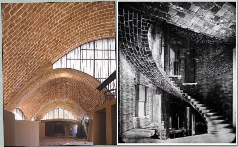
是不是很惊叹?砌块接缝之间的抗剪承载力这么小,如何能实现大跨且异形的结构呢?
Let’s compare two simple mechanics diagrams:
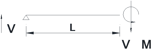
以上是一根简单的简支梁的任意位置的内力分析简图。梁的任意位置存在一个竖向力V。梁截面任意位置的M=V×L(式1),梁支座与截面所承担的剪力共同组成了一个力偶。为了使结构受力达到平衡,必须有一个弯矩来平衡这个力偶。而这个力偶只能通过由梁截面承担的弯矩来平衡。
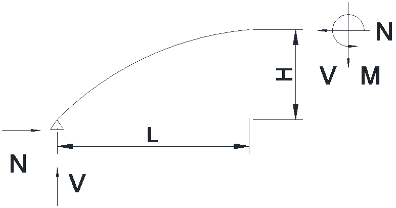
再来看一个拱的内力简图,M+N×H=V×L(式2)。空间拱形结构同时有梁截面弯矩以及一对水平力形成的力偶共同平衡竖向力所形成的力偶。当N×H=V×L(式3)时,截面完全不存在抗弯的需求。此时,结构通过轴力来抵抗外力引起的弯矩。 Let us compare the above internal force diagrams of simply supported beams and arch structures from two dimensions: (1)对比以上简支梁和拱,简支梁利用梁截面自身承担的弯矩,而拱利用轴力以及结构形状引起的力矩来抵抗外力造成的弯矩。从结构承担力矩的效力而言,仅靠截面自身内部拉压形成的弯矩远不及全截面轴力与相对较大的力矩形成的弯矩。
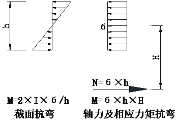
From this point of view, the arch structure can resist large bending moments through axial force. At the same time, comparing Equations 2 and 3, the left-hand term T×H>>M means that the arch structure can bear a larger span. (2) Compare Formula 2 and Formula 3 again. The terms on the left are N×H+M and T×H respectively. In Formula 2, the existence of M causes unevenly distributed stress inside the section, which may also cause local tension and compression in the section. Since the tensile capacity of concrete or masonry structures is extremely weak, this uneven distribution should be avoided as much as possible. Therefore, the internal force state of Formula 3 is our final ideal choice. However, in Formula 3, for the structure, H and L are determined by the shape of the structure. Only when H and L meet the relevant dimensional requirements can the structure satisfy the state of fully resisting the bending moment caused by external loads through axial force. Let’s sort out Formula 3 again, V/N=H/L, “H/L”. Do you think of a concept in space structure? Yes, this is the span ratio. The smaller the span ratio, the smaller the bending moment borne by the horizontal force, and the greater the requirement for cross-section bending resistance. Therefore, the specification puts forward relevant limit requirements for the span ratio of the lattice shell structure. The goal of form finding, in the above example, is to find the relationship between H and L. For spatial structures, the goal of form-finding is to put each component of the structure in a state of pure tension and compression under certain specific boundary conditions, so as to maximize the structural efficiency. This state of pure tension and compression only depends on the geometry of the structure and external load distribution, and has nothing to do with other factors.
- Traditional architectural form-finding analysis cases
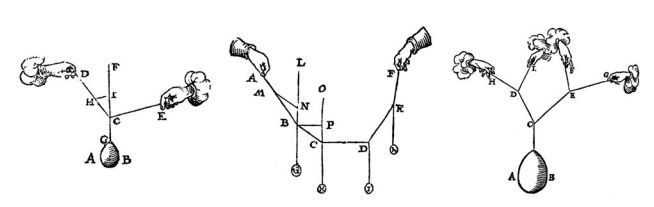
为找到理想的结构形态,工程师们很早就开始了尝试。利用绳索不具备抗弯承载力,只能受拉的特性,在绳索上施加特定的荷载,绳索与荷载所形成的体系就能自动地变形使绳索处于纯受拉状态。这就是我们常说的悬链线法。
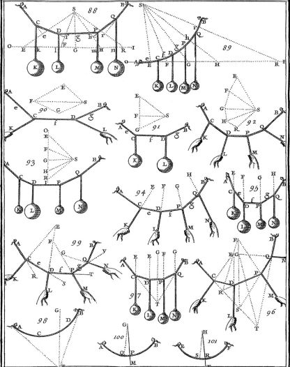
As early as the 16th century, Simon Stevin (1548-1620) made a mathematical demonstration of the catenary method.
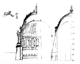
In the 17th century, when Robert Hook (1635-1703) and Christopher Wren (1632-1723) were designing Paul’s Cathedral in London, they used the catenary method to design the masonry structure dome of the church.

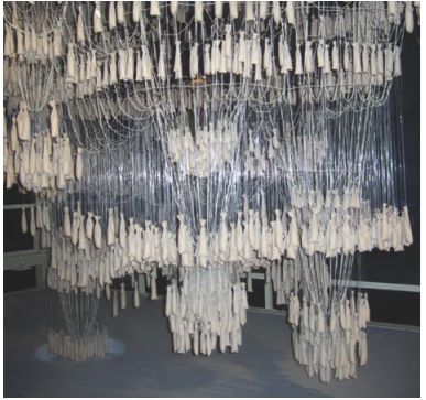
Paul’s Cathedral The Spanish architect Antoni Gaudí (1852–1926) also used form-finding methods when designing the famous Sagrada Familia (Colònia Güell).
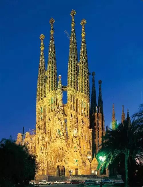
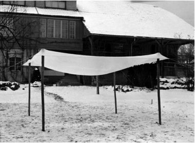
Sagrada Familia 除了利用绳索外,结构工程师们还利用二维连续的材料进行空间结构的找形。 Heinz Isler (1926–2009), an expert in thin concrete shells, pioneered the use of textiles for structural form-finding. For example, in the cold winter, leave a piece of damp cloth outdoors to let it freeze. Ice on the cloth is equivalent to a uniformly distributed load. Finally the corresponding geometric shape is found. By using textile form-finding methods, he designed famous thin concrete shell buildings such as the Grötzingen outdoor theater and Restaurant Los Manantiales.
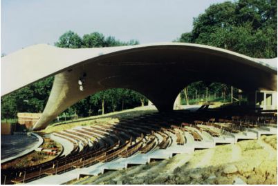
Grötzingen outdoor theatre
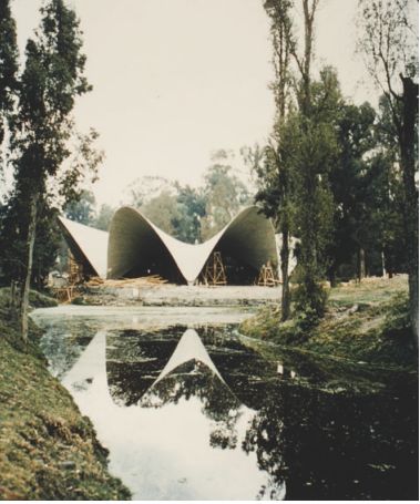
Restaurant Los Manantiales
Frei Otto has also made many highly innovative attempts in structural form-finding since the 1950s. For example, he creatively searches for different structures based on different material properties. For example, when a soap bubble is stretched, the tensile stress at each position is constant, so a structure with uniform stress distribution can be found based on the shape of the soap bubble. The deformation of plastic sheeting usually depends on the strain of the material. The shape of the lattice shell structure mainly depends on the axial deformation of each rod and partly depends on the shear deformation.
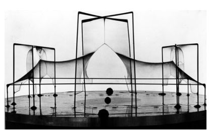
Use soap bubbles to find shapes
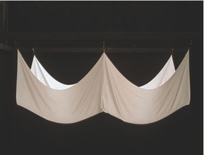
利用塑料布找形
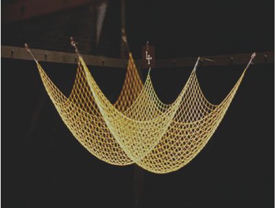
Form-finding using rope woven nets
三、力密度找形的原理
The above attempts were the main methods of early shell structure design. However, with the development of computer technology, the combination of structural design theory and computers is more and more widely used in engineering practice. Structural form-finding analysis can also break away from the complicated form-finding process through experiments and obtain the results we want through numerical analysis. In the previous article “Non-Deconstruction”, “A Brief Introduction to Form-Finding Analysis of Reticulated Shell Structures and Case Appreciation”, we have introduced the method of using the finite element method to perform structural form-finding. Today, we will discuss another numerical analysis method: Force Density Method (FDM). It was proposed by Schek H J in 1974 and improved accordingly by L.Grundi. The characteristic of the force density method is that it only needs to solve a system of linear equations, and the calculation accuracy can meet engineering requirements. The German membrane structure design software EASY uses the force density method to find shapes. Let us understand the basic principles of the force density method through a simple case. The following are nodes P0, P1, P2, P3, P4 and the four members a, b, c, d connected to them. There is load pz acting on P0. Among them, the nodes P1, P2, P3, and P4 are known, and the external load pz is known.
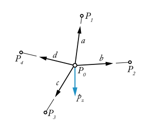
When load pz acts on this system, according to our mechanical foundation, the structure satisfies the following three criteria: (1) According to Hooke’s law, the axial force of each member on the structure is generated due to the deformation of the structure and is proportional to it.
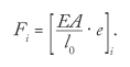
Among them, F represents the axial force, E represents the elastic modulus, A represents the area, l0 represents the original length of the component, e represents the deformation, and i represents the number of the member. (2)构件的长度等于构件两个节点间的距离。

Deformation e is the length difference of the rod before and after deformation.

(3) At each node, the resultant force of all members acting on the node is balanced with the external force. Decompose the internal force of any rod into three forces in the x, y, and z directions. Taking the component in the x direction as an example
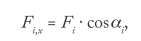
Among them, αi represents the angle between each rod and the x-axis, Fi, x represents the component force in the x direction. The resultant structural force at each node position is 0, and the following equation is obtained:

Converting each cosine term to a coordinate value yields the following equation:

Substituting the Hooke’s law formula into the above equation, we get the following equation:
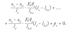
It can be found that x0 and ld in the formula are unknown terms. Although x0 can be solved by simultaneously combining equations in the three directions of x, y, and z, solving such a nonlinear equation system is extremely complicated. Therefore, we introduce the concept of force density to simplify the process of solving equations. Then convert the above formula:

将以下方程定义为力密度qi:
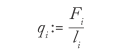
Introducing qi into the original equation, we get:

Finally, the coordinates of point p0 are obtained through transformation:
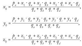
这样,我们就得到了未知点P0的坐标。 The above derivation process is the calculation process of using the force density method to find the shape of a single node. By extending this process to any number of nodes, we can obtain the node coordinates of each coordinate point of the spatial structure after shape-finding. According to the topological relationship between the original structures, the mesh of the form-finding structure can be obtained.
- Force density form finding case
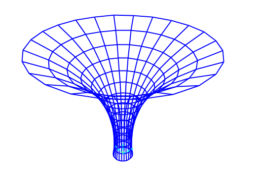
Xiaonong used Python to write a form-finding program using the force density method. The following are several simple structural form-finding cases:

Case 1 before form finding
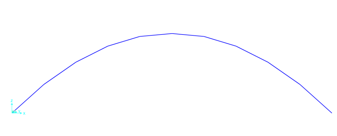
Case 1 After shape finding
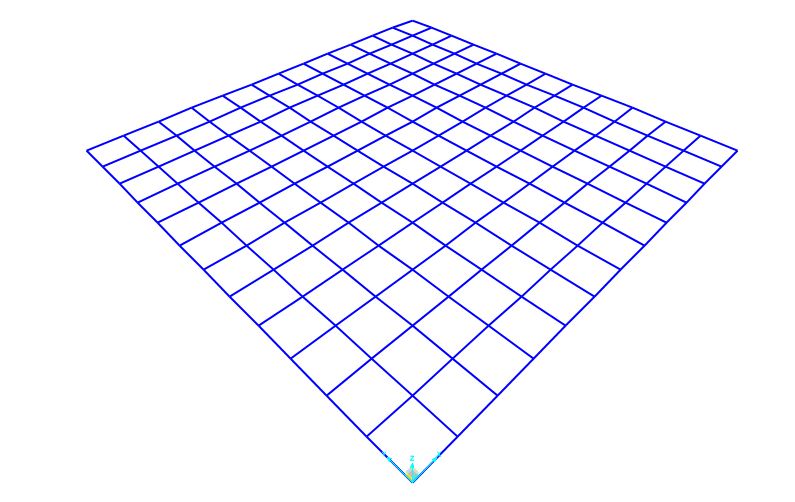
Case 2 before form finding
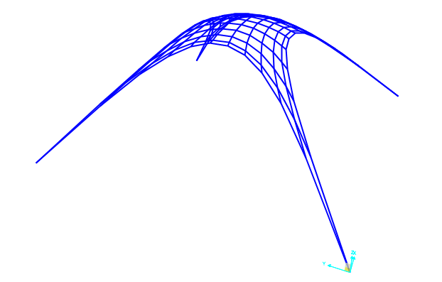
Case 2 After shape finding
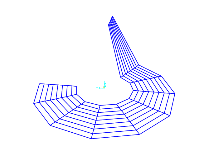
Case 3 before form finding
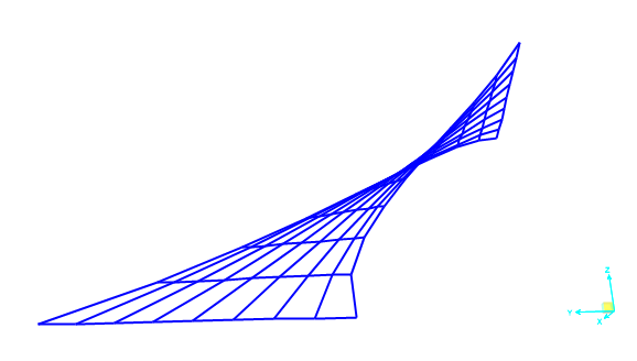
Case 3 After form finding (1)
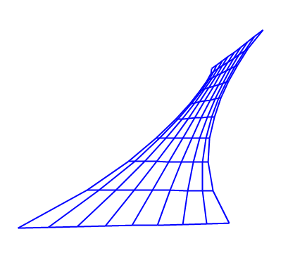
Case 3 After form finding (2)
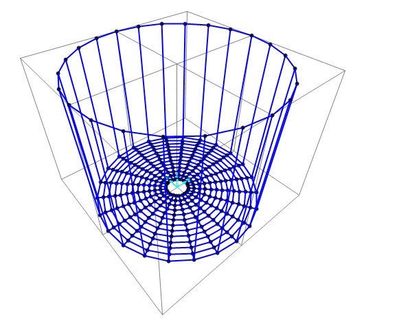
Case 4 before form finding
案例4找形后
- Summary
The purpose of structural form-finding analysis is to find the optimal structural form. In the traditional design process, architects often give full play to their imagination in the concept or plan stage, but ignore whether complex architectural shapes are structurally feasible or optimal. Especially for spatial special-shaped surfaces, the structure is involved in the architectural design at the conceptual stage. The architectural and structural majors work together to find the optimal spatial surface form, which can maximize the effectiveness of this major from both the architectural and structural levels. From an architectural point of view, the shape found in the structure not only brings unexpected beauty, but also maximizes the utilization efficiency of structural materials, meeting the architect’s requirements for larger space and thinner sections. From a structural perspective, it can also optimize the mechanical properties of the structure.
References: shell structure for architecture
Past selections:
Brief discussion on form-finding analysis of lattice shell structure and case appreciation
Collection of cases of layout of 100200m super high-rise structures
200300米超高层结构布置案例集锦
Writing poems on fair-faced concrete in the Seto Inland Sea
On the self-cultivation of structural engineers
佛罗里达州Winter park巨型塌陷──认识岩溶塌陷
Prefabricated concrete structures in New Zealand (Part 1)
The combination of form and force—Zhang Xianliang’s study notes
在CAD里画小圈圈的N种方法—CAD二次开发攻略
划重点 Due to the revision of WeChat, the message function has been unable to be turned on. The editor has also received various private messages in the background. In order to communicate better with everyone, the editor specially left the email [email protected]. The editor has also opened a WeChat ID. If you need to communicate with the editor, please identify the QR code in the picture below to add the editor’s WeChat account.

*This document is automatically collected and organized by AI from non-deconstructed public accounts and is for learning reference only. *
LOADING…