在CAD里画小圈圈的N种方法—CAD二次开发攻略
在CAD里画小圈圈的N种方法—CAD二次开发攻略
Official Account: Non-Deconstructive · Author: Zhou Wenqi (Venchy)
For all drawing dogs who use CAD to draw, just drawing a circle does not seem to be a difficult task. Click the command bar, click the toolbar, and enter the shortcut key directly… When seeing this title, the drawing dogs may laugh and say Are you kidding me? ! Is this topic worthy of writing a public account? ! !
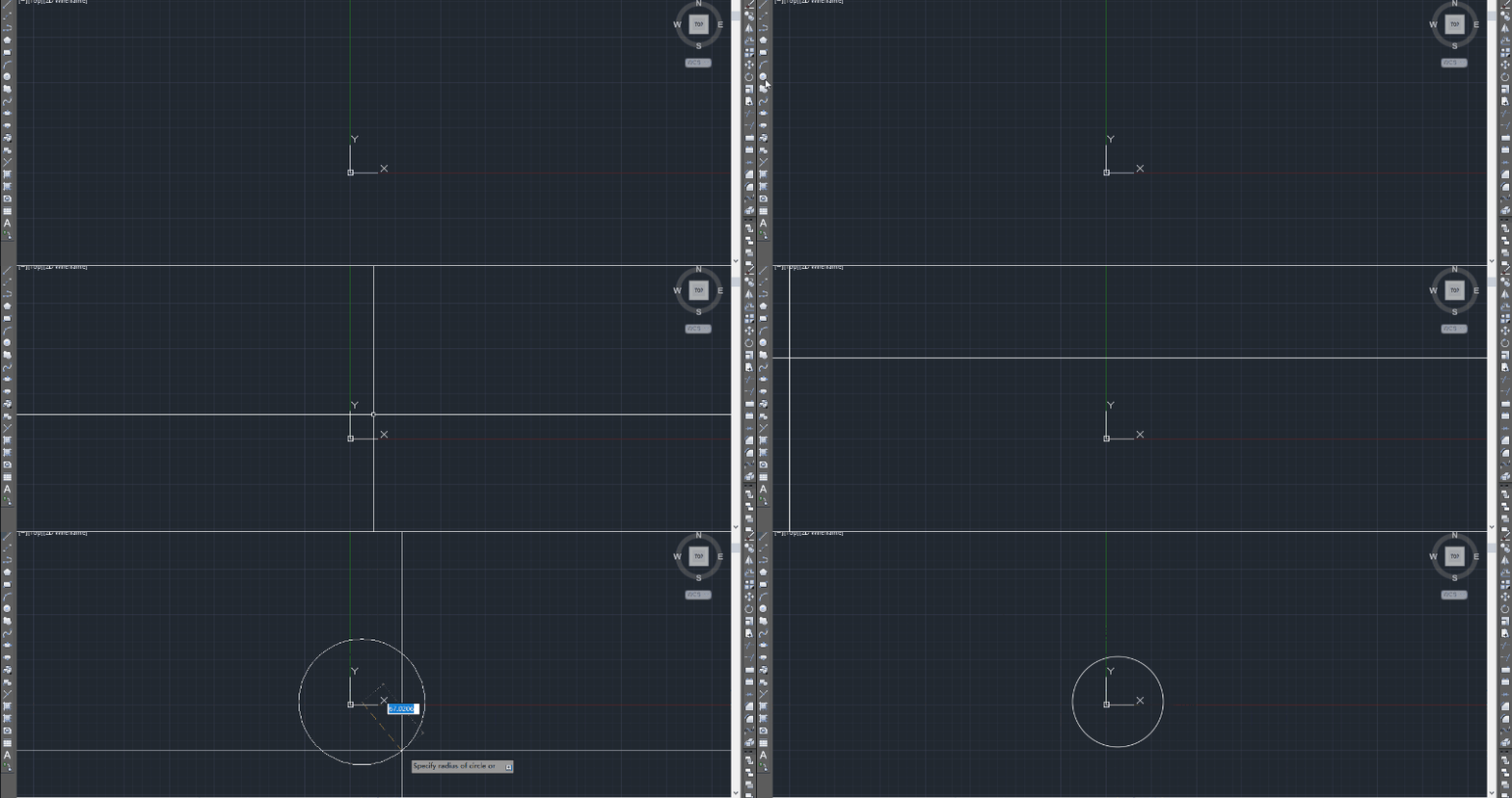
作为非资深画图狗的小编来说,徒手画圈圈当然不在话下。但是,难道AutoCAD只提供给我们这样机械的操作?!是否能够有我们尚未发现领域值得我们去钻研一番?今天,小编就用画圈圈这个案例,和大家共同探讨一下在AutoCAD上做二次开发的N多种可能性。
- LISP
LISP is a general-purpose high-level computer programming language that has long monopolized applications in the field of artificial intelligence. As a language designed for artificial intelligence, LISP is the first declarative functional programming language, which is different from the imperative procedural C, Fortran and object-oriented structured programming languages such as Java and C#. AutoLISP is a LISP programming language developed by Autodesk. LISP is the abbreviation of List Processor. Through autolisp programming, engineers can save a lot of time. AutoLISP language, as an intelligent programming language embedded in AutoCAD, is an indispensable tool for developing and applying AutoCAD. Among them, there are many ways to draw a circle using only the AutoLisp language for secondary development:
(1) COMMAND command
Open the AutoLisp secondary development IDE through tool-》autolisp-》visual lisp editor under the cad interface. A particularly simple programming method provided by Lisp is to use the “command” command.
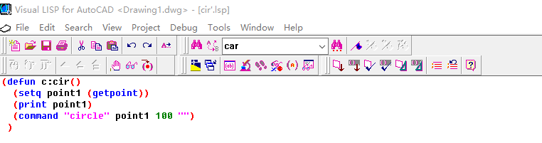
Under the command command, you only need to serialize your mouse operation process into a string of codes in the CAD interface, and you can complete a series of operations at once. The disadvantage is that only one command can be run at a time. The code for drawing a circle is as follows:
(defun c:cir() (setq point1 (getpoint)) ;define center point of the circle (command “circle” point1 100 "");command )
Save the lisp file and drag it into cad or load it through the netload command. With only two simple lines of code, you can complete the drawing of a circle.
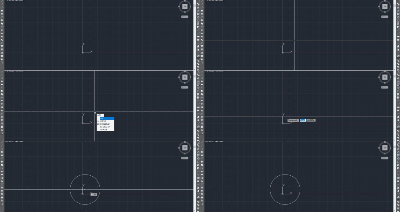
(二) ENTMAKE命令
From the perspective of Lisp language, each CAD primitive is a collection of a series of attributes. Such a collection of attributes is defined as an entity group. Each entity group has a string of codes. Let’s read the entity group code for a regular circle:
((-1 . <Entity name: 7ff422e04d60>) (0 . “CIRCLE”) (330 . <Entity name: 7ff422e039f0>) (5 . “266”) (100 . “AcDbEntity”) (67 . 0) (410 . “Model”) (8 . “0”) (100 . “AcDbCircle”) (10 17.5337 30.5646 0.0) (40 . 100.0) (210 0.0 0.0 1.0))
Among them, (0 . “CIRCLE”) represents the entity group as a circle, and (10 17.5337 30.5646 0.0) represents the center of the circle… . Just read the relevant instructions to read the meaning of each entity group code. So, can we use related entity groups to generate a circle in CAD? The entmake command can achieve this purpose. The following is the code for drawing a circle using the entmake command:
(defun c:cir() (entmake ’( (0 . “CIRCLE”) ;define circle (62 . 1) ;define color (10 0.0 0.0 0.0) ;define center (40 . 50.0) ; define radius ) ) )
Or load lisp first, enter the command, and you’re done.
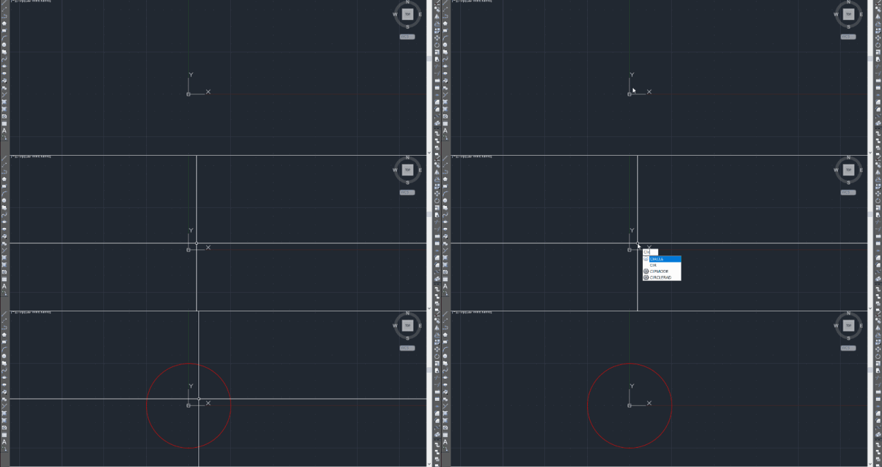
(3) Reactor
A reactor is a simple link between AutoCAD and the user’s application, which allows functions to respond to events that occur within AutoCAD. For example, you can create a reactor to notify the user’s application that a primitive has been deleted. At this time, the application will perform some actions to respond to this event. A button on a form is a simple example of an event-driven program that uses events and responses to perform actions. When the button is selected, it activates an event, like a signal or broadcast. The event is detected by the reactor and the resulting action is performed using a process called a callback. Here is the code to draw a circle using the reactor:
(defun c:cir() (setq thisdrawing (vla-get-activedocument (vlax-get-acad-object))) ;get drawing object (setq mspace (vla-get-modelspace thisdrawing));get model space (setq pt1 (vlax-3d-point (getpoint “\nCenter point: ”)));define center of circle (vla-AddCircle mspace pt1 50) ;add circle )
- VBA
Visual Basic for Applications(VBA)是Visual Basic的一种宏语言,是微软开发出来在其桌面应用程序中执行通用的自动化(OLE)任务的编程语言。主要能用来扩展Windows的应用程序功能,特别是Microsoft Office软件。VBA同时也是AutoCAD的集成开发环境,VBA的加入扩展了AutoCAD的集成用户化能力。AutoCAD的开发环境也是一个可视化开发环境。
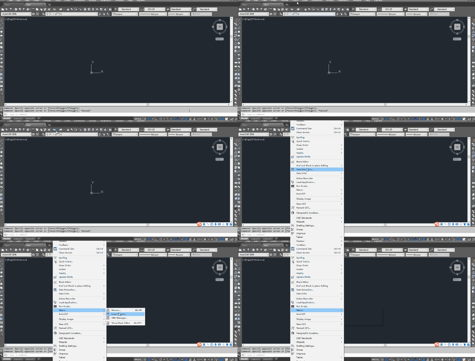
But when we try to open the VBA IDE in AutoCAD, it often prompts that there is no related program. This is because since AutoCAD2010, AutoCAD has canceled the VBA IDE interface. If you want to use VBA for secondary development of AutoCAD, you need to install the AutoCAD VBA enabler. The download address is as follows: (1)http://www.autodesk.com/vba-download (2)http://www.cad8.net/thread-12322-1-1.html 当安装完成后,重复之前的操作或者在cad命令行输入vbaide,于是就出现了如图所示cad界面下的VBA的IDE
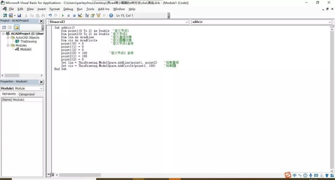
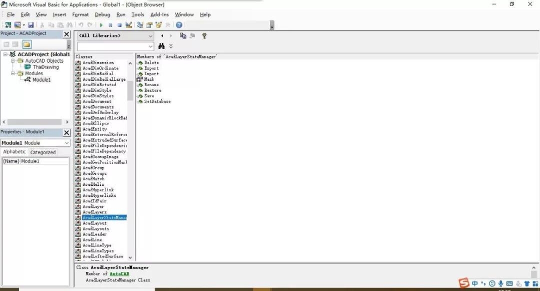
This interface is exactly the same as the VBA interface in Excel. If you feel a little helpless, enter F2, as shown in the figure below, and the paths for various functions of AutoCAD’s VBA secondary development will appear.
下面就是利用VBA在AutoCAD中绘制圆形的代码:
Sub addcir() Dim point1(0 To 2) As Double ‘define point1 Dim cir As AcadCircle ‘define circle object point1(0) = 0 ‘define coordinate of point1 point1(1) = 0 point1(2) = 0 Set cir = ThisDrawing.ModelSpace.AddCircle(point1, 100) End Sub
The following is the drawing process:
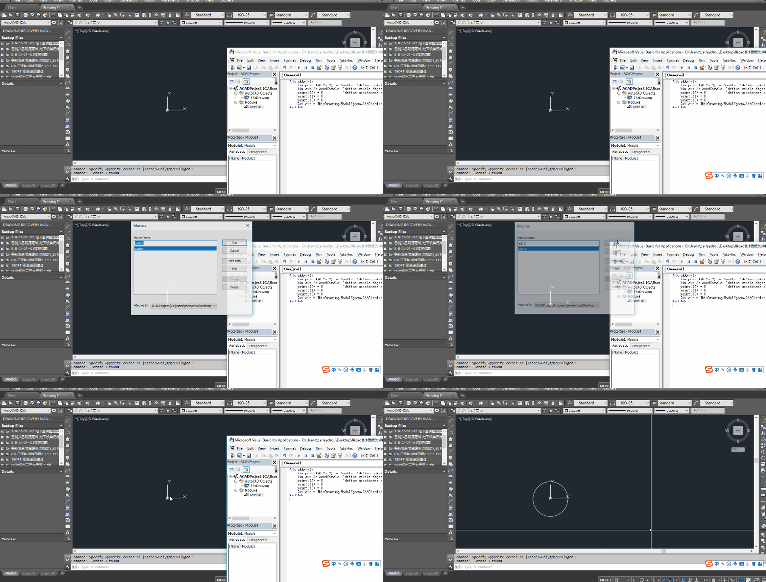
大功告成!
三、C#.NET
As for the VBA and VLisp mentioned earlier, their advantages and disadvantages are obvious: ObjectArx is powerful and has high programming efficiency, but its disadvantage is that programmers must master VC++, and this language is very difficult to learn; although VBA and VLisp are simple and easy to use, they seem to be incapable of developing large programs. So is there a language that can combine their advantages and try to avoid their shortcomings? The answer is yes, that is Microsoft’s new 21st century programming language C#. C#是通过AutoCAD ActiveX 这座桥梁来和AutoCAD之间进行通讯的。AutoCAD ActiveX 使用户能够从 AutoCAD 的内部或外部以编程方式来操作 AutoCAD。它是通过将 AutoCAD 对象显示到“外部世界”来做到这一点的。一旦这些对象被显示,许多不同的编程语言和环境就可以访问它们。关于AutoCAD ActiveX 的情况,大家可以参考AutoCAD自带的帮助。
关于C#对AutoCAD二次开发环境的说明: Due to the continuous upgrading of AutoCAD’s development framework, different versions of CAD need to correspond to different versions of the netframework framework, and correspondingly to different Visual Studio. The requirements for each development version are as follows:
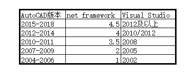
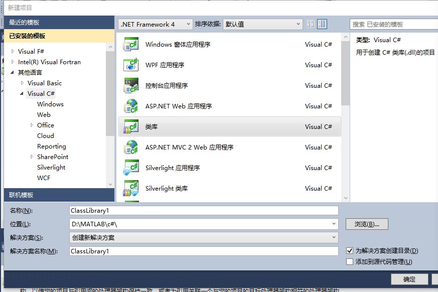
The editor’s development environment is Visual Studio 2010 version and AutoCAD 2012. Development process: (1) Create a class library in VS.
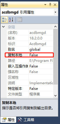
(2) Reference CAD internal assemblies, including acdbmgd.dll, acmgd.dll, AcCui.dll and accoremgd.dll, etc. It should be noted that after adding the reference, you need to right-click the reference property and adjust Copy Local to false.
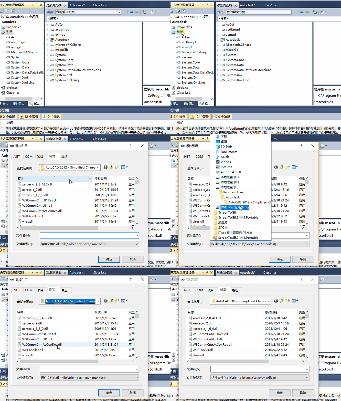
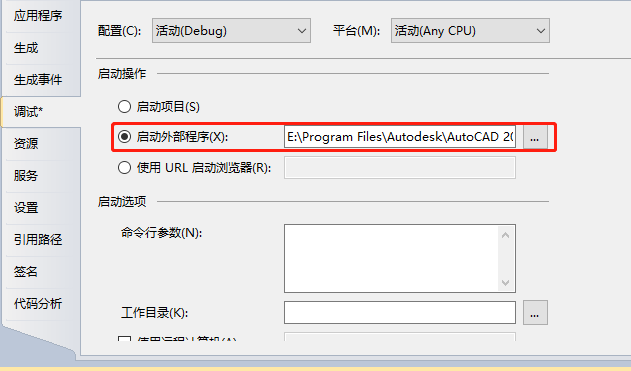
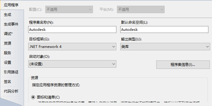
(3) Set the target framework and debugging method. Right click on the selected project and select Properties. Choose the appropriate external program (acad.exe) and the appropriate framework.
The following is the code for drawing a circle using C#.net:
using System; using System.Collections.Generic; using System.Linq; using System.Text; using Autodesk.AutoCAD.DatabaseServices; using Autodesk.AutoCAD.Geometry; using Autodesk.AutoCAD.Runtime;
namespace Autodesk { public class Class1 { [CommandMethod(“Drawcir”)] //Define circle drawing function public void Drawcir() { //Get the current active graphics database Database db = HostApplicationServices.WorkingDatabase; //Define the center of the circle Point3d stPoint = new Point3d(0, 0, 0); //Define circle Circle cir= new Circle(stPoint,Vector3d.ZAxis,100); using (Transaction tr = db.TransactionManager.StartTransaction()) { BlockTable bt = (BlockTable)tr.GetObject(db.BlockTableId, OpenMode.ForRead); BlockTableRecord btr = (BlockTableRecord)tr.GetObject(bt[BlockTableRecord.ModelSpace], OpenMode.ForWrite); //Add the circle to the block table. This method has a return value and can return the id of the entity object btr.AppendEntity(cir); //Add the object to the transaction tr.AddNewlyCreatedDBObject(cir, true); //Submit transaction processing tr.Commit(); } } } }
Special attention needs to be paid to the several pieces of code added in orange. 代码编写完成,在项目右键生成,相应的项目路径的bin文件夹下会生成该项目的dll文件。在cad中利用netload命令加载相关dll文件,就可以得到相关成果。
- Extra chapter
In addition to the above methods, CAD also provides secondary development methods such as C++ and VB. The figure below shows the ability and learning difficulty of developing CAD in various languages.

In terms of programming learning efficiency and ease of use, various programming languages have their own strengths and weaknesses. Everyone can choose different methods to carry out related secondary development according to their own needs. Judging from the numerous CAD plug-ins in your collection, the utility of mastering a secondary development language of AutoCAD is self-evident. The feeling of pleasure when using plug-ins written by myself is much greater than using Explorer Shenma!
References: Wilson Wu .NET-based CAD secondary development (introduction) Structural Utopia https://mp.weixin.qq.com/s/i2Ql_5-yI0Lv7ZpfByCYOw
Past selections: The roof of the Sydney Opera House is not a thin shell structure? ? 吴哥石构建筑的精髓-叠涩拱 基于ABAQUS的参数化分析方法及案例 Straight lines belong to humans, but curves belong to God! One-click drawing and batch binding - CAD you don’t know Collection of cases of layout of 200~300m super high-rise structures Brief discussion on form-finding analysis of lattice shell structure and case appreciation Grasshopper可视化编程初步 YJK钢结构节点设计内力读取工具

*This document is automatically collected and organized by AI from non-deconstructed public accounts and is for learning reference only. *
LOADING…