基于ABAQUS二次开发的钢结构支撑端节点板式节点板参数化分析
Parametric analysis of steel structure support end gusset plate based on secondary development of ABAQUS
Official Account: Non-Deconstructive · Author: Zhou Wenqi (Venchy)

Strong nodes and weak components are the general principles of building structure design. Steel structure node connection In the design of steel structure, there are two main ways of connecting beam-column nodes with diagonal braces, as shown in Figure 1 and Figure 2. Among them, the node connection method shown in Figure 1 basically maintains the original shape of the component at the node, and its load-bearing capacity is relatively reliable. However, its production and construction are relatively complex, and the sizes of the rods supported by the beams and columns need to match. Node 2 only needs a node plate to connect to the component, which is easy to construct. The diagonal brace can use rods of any cross-section, which solves this problem. Compared with node 1, its force is closer to an ideal hinge and will not produce a large secondary bending moment in the structure [1]. At the same time, the stiffness of node 2 is also smaller than node 1, which will not cause the support deformation to be too concentrated in the middle of the support, which is beneficial to improving the low-cycle fatigue life of the support. However, the current research on the mechanical performance of plate gusset plates is not comprehensive.

图1 节点1

Figure 2 Node 2
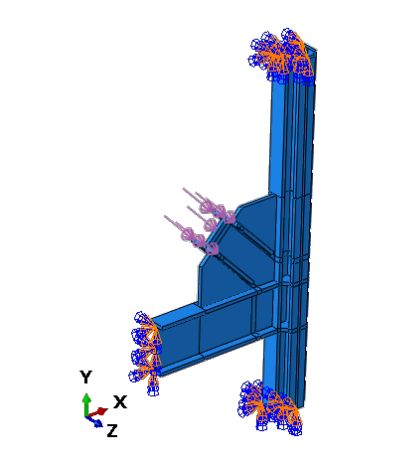
图3 节点2有限元模型
Whitmore proposed that the axial force of the diagonal brace propagates according to a diffusion angle of 30°, and based on this, the effective width of the gusset plate is determined to determine the bearing capacity of the gusset plate [2]. Tsai et al. found that the deformation shape of the gusset plate at the connection between the herringbone support and the beam is similar to the buckling shape when the end of the gusset plate has only a low rotational stiffness provided by the support, which is inconsistent with the assumption that the end of the gusset plate has infinite rotational stiffness commonly used in analysis [3]. Zhang Wenyuan and others simulated a large number of nodes with different member sizes. Based on the effective length of the gusset plate, the thickness of the gusset plate, the support angle, and the stability theory of steel, they proposed a recommended formula for the bearing capacity of plate gusset plates based on the simulation results [4][5].
本文通过ABAQUS二次开发建立不同的模型,对板式节点板进行参数化分析,研究对板式节点板的受力性能有影响的相关因素,并给出相关的设计建议。
1 Model overview and ABAQUS parametric modeling
1.1 Overview of analysis model
The structural model in this article is shown in Figures 2 and 3: among them, the cross-section dimensions of beams and columns in all models remain unchanged, and the beam cross-section is I1000×350×50×70. The column cross-section size is 700×700×350×350×50×70. The diagonal brace cross-section is I700×700×80×70. The cross-section of the connection part between the gusset plate and the diagonal brace is the same as that of the diagonal brace.
In abaqus, Q235 is selected as the steel material, the elastic model is 2.06×10⁵MPa, the Poisson’s ratio is 0.3, and the bifold line model is selected as the material. The model is modeled using solid unit C3D8R. The beam end and column end sections are rigidly connected, and the axial force of the diagonal brace is applied to the end of the diagonal brace. Loading is divided into two analysis steps. The first analysis step uses standard general, which is a preload of 0.01N/mm2. The second analysis step uses standard riks, which applies gradually increasing axial force to the end of the diagonal brace to determine the critical buckling load of the gusset plate.
1.2 ABAQUS parametric modeling
The workload of building a large number of models using the GUI that comes with abaqus/cae is huge. Therefore, this article uses the abaqus scripting interface, which is customized and developed based on the Python language. Using this interface for parametric modeling of nodes can greatly improve the efficiency of node analysis.
Based on the Python language, the abaqus script interface adds many new object models, corresponding to various functions of the abaqus/cae gui interface. This article defines the relevant parameters of the gusset plate as basic variables. The main objects used in the parametric modeling process are as follows: (1) ConstrainedSketch: used to create sketch objects. (2) Material.Density/Elastic/Plastic: used to define material properties. (3) BaseSolidExtrude: used to create Part based on sketch. (4) rootAssembly.Instance.translate/rotate/merge: used for movement, rotation and merging when assembling objects. (5) StaticStep/ StaticRiksStep: used to define analysis steps (6)PartitionCellByPlaneThreePoints/setElementType/ seedPart/ generateMesh:用于切割模型及划分网格 (7) Pressure/EncastreBC: Define loads and boundary conditions (8)Job:定义计算模型
2 Ultimate bearing capacity of nodes
2.1 不同的几何尺寸的节点板的承载力
本文以节点板对应斜撑翼缘的伸入节点板的长度Lb,角度α(如图2所示)分别建立了15个模型。各模型具体参数见表1。
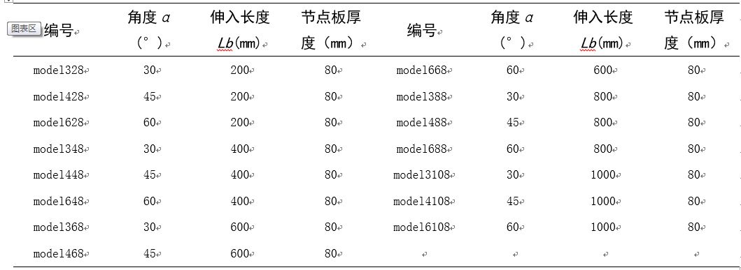
Table 1 Model numbers with gusset plate size as variable
According to a large number of numerical simulations in literature [4], the calculated length coefficient of the gusset plate is given. The calculation is based on formula 1 to calculate the steel structure length coefficient μ, and then combined with the steel structure specifications to determine the corresponding stability coefficient ψ, and the bearing capacity of the gusset plate is obtained according to formula 2.

Appendix F of “Code for Design of Steel Structures” (GB 50017-2003) [7] gives the calculation formula for the bearing capacity of truss structure gusset plates under the action of diagonal web members.
综合钢结构设计规范,文献[4]及本文数值模拟的结果,得到的各几何参数下节点板的极限承载力如图4所示。
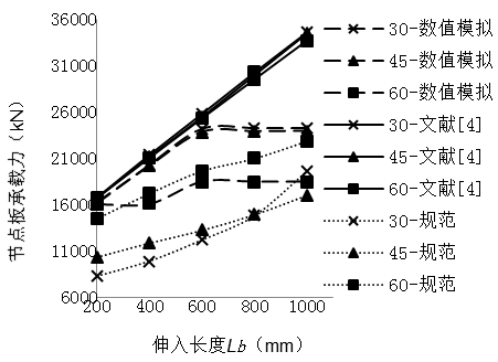
图4 各种计算方法得到的屈曲荷载
From a numerical perspective, the bearing capacity of the gusset plate calculated according to the steel structure code is the smallest. Therefore, the bearing capacity of generally supported plate gusset plates designed in accordance with Appendix F of the Steel Structure Code is conservative. The bearing capacity of the gusset plate calculated according to the specifications and literature [4] increases with the increase of the diagonal bracing flange extension length Lb. The analysis of numerical simulation shows that when the extension length Lb of the diagonal brace is 200~600mm, the bearing capacity of the gusset plate increases with the increase of the extension length, and the trend is similar to the results calculated in the literature [4]. However, when the extension length Lb is greater than 600mm, the bearing capacity of the gusset plate tends to remain unchanged.
Judging from the size of α, the bearing capacity of the gusset plate at each angle calculated according to the literature [4] is similar; the bearing capacity at 30 degrees and 45 degrees calculated according to the specification is similar and smaller; in the results of numerical simulation, the bearing capacity of the gusset plate when α is 30 degrees and 45 degrees is similar, and when α is 60 degrees, its bearing capacity is about 20% smaller than the other two angles.
2.2 破坏形态
Figures 5 to 12 show the stress cloud diagrams of model428, model4108, model3108 and model6108 before and after node buckling.
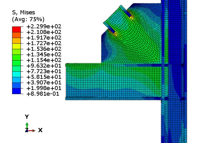
Figure 5 model428(1)
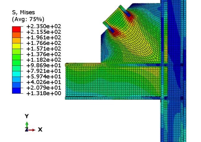
图6 model428(2)
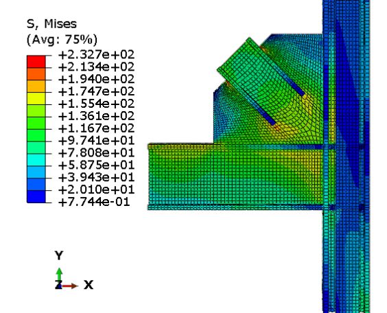
图7 model4108(1)
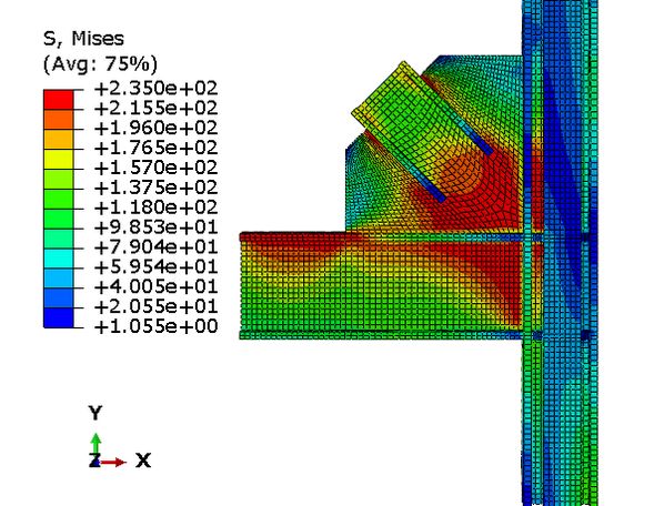
Figure 8 model4108(2)
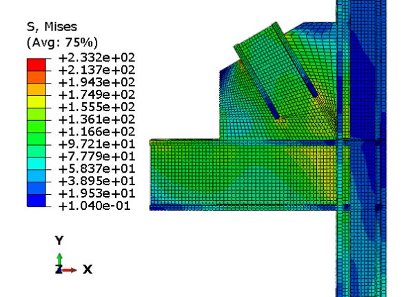
Figure 9 model3108(1)
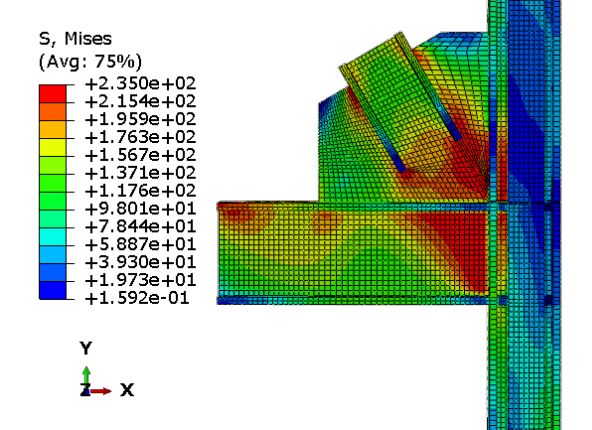
Figure 10 model3108(2)
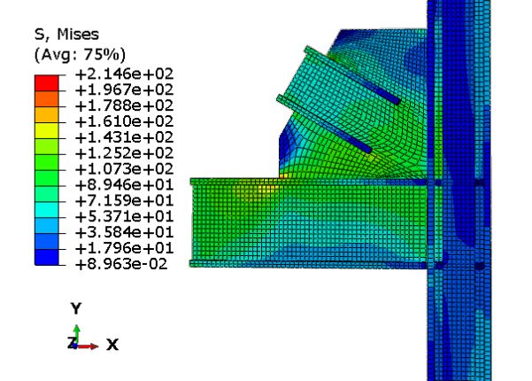
Figure 11 model6108 (1)
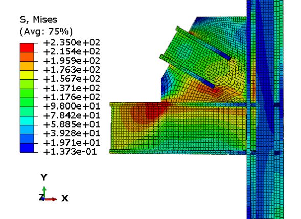
Figure 12 model6108(2)
Comparing Figure 5 and Figure 6, when the extension length Lb of the diagonal brace is 200mm, the gusset plate buckles at the two flange ends of the diagonal brace. In the area other than the local damage of the gusset plate, the stress of the gusset plate in the extension part of the diagonal brace web is larger, but it decreases with the increase of the distance from the diagonal brace flange. The gusset plate stresses in other areas are smaller.
Comparing Figure 7 and Figure 8, when the extension length Lb of the diagonal brace is 1000mm, the gusset plate undergoes overall buckling at the end of the diagonal brace. At the same time, the damage to the gusset plate is not limited to the gusset plate. The beam and column webs connected to the gusset plate are all damaged, and the internal force value of the beam and column flange is not large. It shows that under this failure mode, the gusset plate has a great influence on the stress of the beam and column webs connected to it. Comparing Figure 9 and Figure 10, the failure shape of the gusset plate of model3108 is similar to that of model4108, but the buckling part is biased towards the column side.
Comparing Figure 11 and Figure 12, the model6108 node buckling did not occur on the gusset plate, but at the end of the gusset plate at the interface between the gusset plate and the beam. Local buckling failure of the beam occurred. The internal force of the gusset plate close to the beam side was larger, but it did not yield. It shows that when the internal force is too large, in addition to causing damage to the gusset plate itself, the plate gusset plate can also cause local damage to the beam.
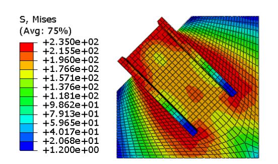
图13(a) 文献[4]模型破坏形态
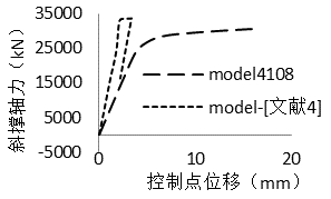
Figure 13(b) model4108 and reference [4] model displacement load curve
The results calculated according to the literature [4] in Figure 4 are quite different from the results of the numerical simulation in this paper, which is also related to the failure form of the gusset plate. Figure 13a shows the stress distribution of the gusset plate after node buckling based on the geometric parameters of the gusset plate modeled in literature [4] and model4108. This node does not consider the effect of beams and columns on the gusset plate, and only imposes constraints on the boundaries of the gusset plate. Compare Figure 6, Figure 8 and Figure 13. In Figure 13, the damage to the gusset plate mainly occurs at the intersection between the diagonal brace and the gusset plate. The failure form of the gusset plate in Figure 13(a) is similar to Figure 6, but is quite different from the failure form of the gusset plate in Figure 8. At the same time, comparing the displacement load curves of model 4108 and the literature 4 model (Figure 13b), the ultimate bearing capacity of the literature [4] model is 33000kN, which is much larger than the numerical model in this paper, but its deformation capacity is poor. When the displacement is 3.5mm, the node loses its bearing capacity. In Figure 4, the bearing capacity of nodes with similar failure forms to Figure 13 is similar to that of Reference [4], while the bearing capacity of nodes with different failure forms from Figure 13 is quite different from that of Reference [4]. Therefore, the different damage forms caused by different boundary conditions make the calculation results of some nodes in this paper and the literature [4] quite different.
- Internal force transfer between diagonal braces and gusset plates
From the perspective of force transmission, the internal force transmission from the node plate to the node beam-column node can be divided into two parts. The first is the internal force transfer between the diagonal brace and the gusset plate. The second is the internal force transfer between the gusset plates and beams and columns. For the convenience of observation, the total axial force of the orthogonal section of the node as shown in Figure 14 is defined as Na, the axial force borne by the node flange section is Nf, and the axial force borne by the node plate section is Nw, that is, Na=Nf+Nw. Nf=ΣNfi.
In order to study the internal force transfer between the diagonal brace and the gusset plate, as shown in Figure 14, the axial force Na of each section when the node buckles under the action of axial pressure is extracted according to Ln, and the internal force distribution diagram is shown in Figures 15 to 17. In order to study the distribution ratio of the axial force borne by the diagonal brace flange part and the gusset plate part of each joint section, the relationship curve between the axial force Nf and Ln of the joint flange part of each joint model is extracted, as shown in Figures 18 to 20. The relationship between the axial force Nw and Ln borne by the gusset plate is shown in Figures 21 to 23.
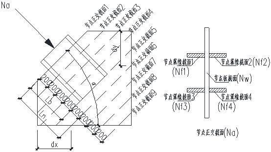
Figure 14: Each orthogonal section for extracting axial force
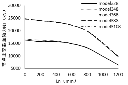
Figure 15 Axial force of node orthogonal section when α=30°
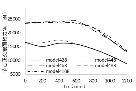
Figure 16 Relationship between Na and Ln when α=45°
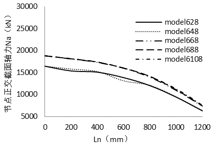
Figure 17 Relationship between Na and Ln when α=60°
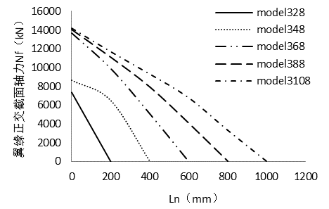
Figure 18 Relationship between Nf and Ln when α=30°
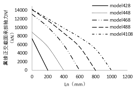
Figure 19 Relationship between Nf and Ln when α=45°
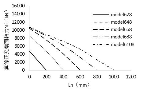
图20 α=60°时 Nf与Ln关系
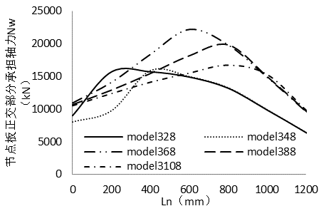
图21 α=30°时 Nw与Ln关系
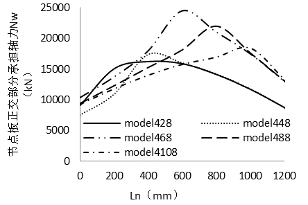
Figure 22 Relationship between Nw and Ln when α=45
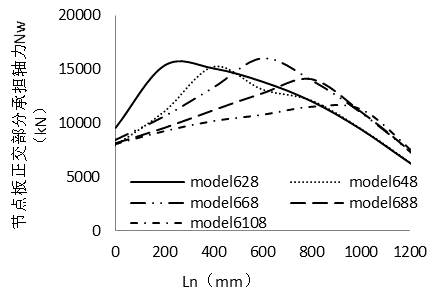
Figure 23 Relationship between Nw and Ln when α=60°
3.1 When the joint plate and flange are jointly stressed, the attenuation trend of the joint orthogonal section axial force Na with Ln
The gusset plate plays the role of interconnecting the beams, columns and diagonal braces. The internal force of the diagonal brace is transmitted to the beams and columns connected to it through the node. From Figure 15 to Figure 17, the changing trend of the axial force on the node plate is obtained:
(1) When Ln is less than 800mm, the change of the axial force Na of each orthogonal section of the node along Ln is not obvious. When Ln is greater than 800mm, the axial force Na of each orthogonal section decreases as Ln increases. It can be found from Figure 14 that when Ln is less than 800mm, the orthogonal section of the node cannot intersect with the beams and columns, dx and dy are both 0, and the axial force of the diagonal brace cannot be transmitted to the beams and columns. When dx and dy are greater than 0, the axial force of the diagonal brace borne by the gusset plate can be partially transmitted to the beams and columns. The axial force on the gusset plate shared by the beams and columns increases with the increase of dx and dy.
(2)节点板传递给梁柱的内力不随斜撑的伸入长度Lb的变化而变化。当Ln为0时,节点正交截面的轴力与节点的屈曲荷载相当。图15至图17中,Lb为200及400的各条曲线几近重合;Lb为600,800,1000的各模型也接近重合。说明斜撑的伸入长度Lb对节点正截面轴力Na不起作用。
(3)正交截面轴力越大,节点板传递给梁柱的内力随Ln衰减的越快。图15至图17,中各条曲线所示,屈曲荷载为24000kN的模型轴力沿Ln的分布曲线的效率明显大于屈曲荷载为16000kN的模型。
3.2节点翼缘部分传递内力给节点板时,节点翼缘截面承担的轴力Nf随Ln的衰减趋势
In the section Lb where the diagonal brace flange extends, the axial force Na on the orthogonal cross section consists of two parts: the axial force Nw of the gusset plate and the axial force Nf of the diagonal brace flange part. The reduced axial force in the flange part is transferred to the gusset plate through the shear stress between the flange and the gusset plate. From Figure 18 to Figure 20, the curve relationship between the axial force Nf and Ln borne by the flange part of the diagonal brace is obtained.
The flange axial force Nf gradually decreases as the length Ln increases, and the relationship between the two approaches linearity. The axial force borne by the flange is transmitted to the gusset plate in the form of shear stress, so the shear stress values at various positions of the gusset plate and the flange tend to be constant. At the same time, comparing the slopes of each curve, when the length of Lb is larger, the slope of the curve is smaller, indicating that under the same flange axial force, the shear stress on the interface between the flange and the gusset plate decreases as Lb increases.
以model428与model4108为例,model428的翼缘和节点板的交接面在Lb=200mm的长度上要承担7409kN的翼缘部分轴力,其剪切应力为τ=132.5Mpa。而model4108虽然在翼缘截面上要承担14260kN的轴力,但其剪切应力仅为τ=50.92Mpa。综合考虑轴力与剪力的影响,model428容易在节点板与翼缘的交接面因剪切应力过大发生局部失稳破坏(图5,图6),而model4108在Lb处发生节点板的整体失稳破坏(图7,图8),且其临界荷载远大于model428。Lb等于200mm及400mm的其他节点的破坏原理同model428。因此建议在验算节点时,节点板与翼缘的交接面上的承载力,避免节点的局部破坏。
3.3 节点板截面承担的轴力Nw沿Ln的分布
The total axial force Na of the node orthogonal section, minus the axial force Nf of the flange section where the diagonal bracing flange extends into the section, is the axial force Nw borne by the node plate. The relationship curve between the axial force Nw and Ln borne by the gusset plate section is shown in Figures 21 to 23. It can be found that the peak internal force of each curve occurs at Ln = Lb, that is, when the overall buckling failure of the gusset plate occurs, the maximum position of the axial force Nw of the gusset plate of each model occurs at the length of the diagonal brace extending into the gusset plate Ln = Lb. When the node buckling load is the same, the greater the length of Lb, the smaller the maximum axial force Nw that the node plate bears at Ln. Since there are flange constraints in the range from Ln=0 to Ln=Lb, and the maximum axial force of the gusset plate does not occur in this section, the overall buckling of the gusset plate cannot occur in this section. When Ln>Lb, the gusset plate axial force Nw tends to decrease. When Ln=Lb, the gusset plate not only has to bear the axial force of the gusset plate itself, but also the internal force transmitted to the gusset plate from the flange end. The maximum stress of the gusset plate easily occurs on the section with Ln=Lb. Therefore, when checking the overall stability of the joint plate, it is necessary to use the cross section of Ln=Lb as the control section for checking the overall stability of the joint plate. However, on the section with Ln=Lb, the internal force distribution of the gusset plate is not uniform, and the calculated width of the section needs to be converted.
3.4 Internal force transfer between gusset plates and beams and columns
In Figures 7 to 10, when the plate gusset plate is damaged as a whole, the beam web and the gusset plate connected to the gusset plate are jointly damaged. In Figures 11 and 12, due to the excessive internal force at the plate end of the plate gusset plate, the beam web was damaged first. Therefore, it is necessary to ensure the strength of the beams and columns directly connected to the plate gusset plate.
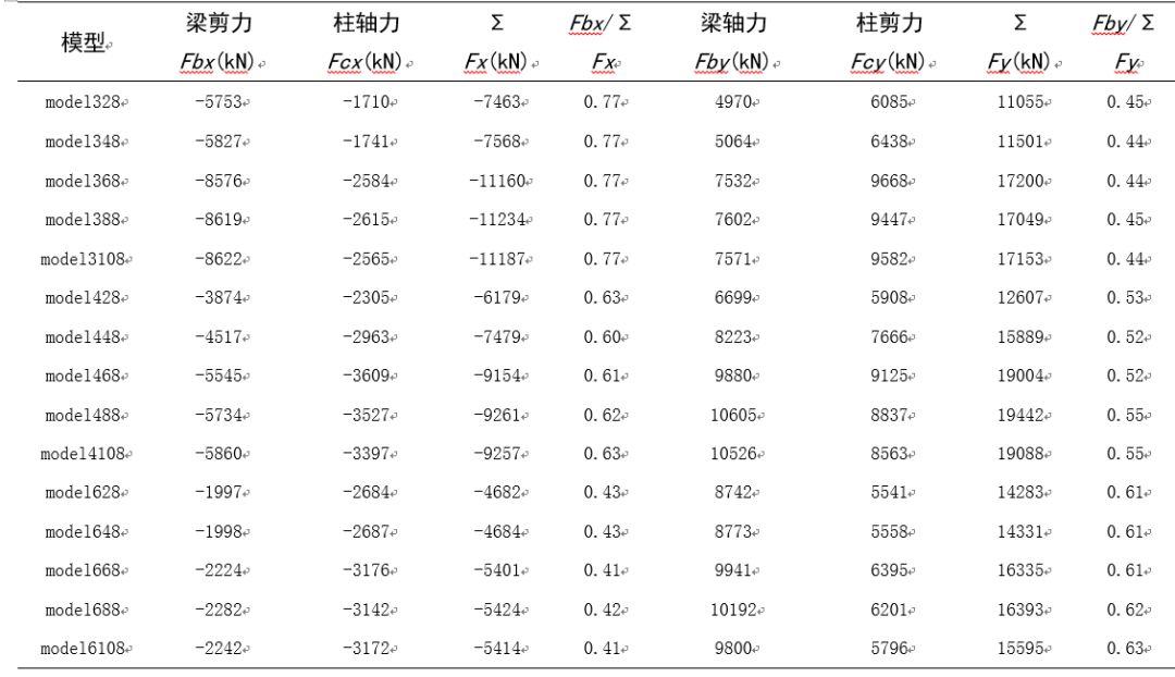
Table 2 Internal force distribution of beams and columns in each model
各节点板与梁柱交接面上分别以剪力及轴力的方式传递给节点周边的梁柱,如图24所示。提取各节点屈曲时节点板与梁柱交接面上的轴力(Fby,Fcx)与剪力(Fbx,Fcy),其值大小如表2所示。斜撑的水平分力由节点板与梁交接面的剪力及节点板与柱交接面的轴力组成,即ΣFx= Fbx+ Fcx。同理,竖向分力ΣFy= Fby+Fcy。计算各节点中节点板轴力与剪力分担的某一方向的合力,如表2所示,发现边界条件相同的情况时,斜撑在某一转角下,梁剪力与柱轴力及柱剪力与梁轴力的分配比例接近于定值。如当α为30度时,各节点板与梁交接面分担的节点水平力与总的水平力的比值为都0.77。因此,在进行设计工作时,建议将斜撑的轴力按照一定的比例进行分配,分别施加于与节点板连接的梁与柱上。对梁柱腹板的局部稳定进行验算。
除了节点板的水平分力和竖向分力外,节点板承受轴力的与梁柱中心线交点的偏心距(如图24所示e)所产生的弯矩也容易对节点板及其周围梁柱的受力产生较大的影响。为保持节点板尺寸的统一,本文各α=60度模型轴力与梁柱中心线交点的偏心距达到了450mmm,因此,其对节点产生较大的偏心距导致节点板各α为60度的模型在节点板与梁的交接面上产生了Mb=1500kN·m的弯矩。根据节点板偏心受压作用下内力计算公式,这样大的弯矩导致节点板板端局部巨大的压应力,从而使梁的腹板在节点板端部发生局部破坏(图11,图12)。因此,在设计过程中,应该避免使斜撑轴力与梁柱中心线交点产生偏心。若无法避免,或者当斜撑截面承受较大的弯矩时,应验算节点板端部应力,避免节点板端部出现较大应力,使梁发生如图11及图12的局部破坏。
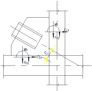
图24 节点板与梁柱的内力传递
4Conclusions and suggestions
通过对不同几何尺寸条件下节点板承载力及内力传递的分析,可以得到以下结论:
(1)节点板的破坏可以分为节点板的局部破坏及整体破坏。其中,局部破坏包括节点板上的局部破坏及与节点板连接的梁柱的局部破坏。
(2)由于节点板翼缘部分承担的轴力较大,当斜撑翼缘与节点板之间的交接面长度过小时,容易使两者的交接面间产生较大的剪切应力,使翼缘与节点板交接面发生局部破坏。因此建议在设计时验算翼缘与节点板交接面上的承载力。
(3) The section with the largest internal force of the gusset plate is located at the end of the flange. When checking the overall stability of the gusset plate, the flange end section can be used as the control section of the gusset plate.
(4)节点板与梁柱交接面上的水平及竖向分力以节点板与梁柱交接面上的剪力与轴力的形式传递。且水平分力及竖向分力按照一定的比例传递为交接面上的轴力和剪力。当节点板整体破坏时,梁柱腹板与节点板共同发生破坏,建议对与节点板相连的梁柱腹板进行稳定性验算。必要时对梁柱腹板进行加强。
(5)轴力与梁柱中心线的交点偏心较大时,容易使得节点板与梁柱交接面上产生较大的弯矩,使梁柱在节点板端部产生较大应力,造成节点板的局部破坏。因此在这种偏心不可避免或者斜撑截面上产生较大弯矩时,建议对节点板与梁柱交接面上的弯矩进行验算,保证梁柱的局部稳定。
References [1] Zhang Wenyuan, Chen Shixi, Zhang Yaochun. Research on low-cycle fatigue analysis and design methods of braces and beam-column plate connection nodes [J], Engineering Mechanics, 2011, 28 (1): 96-104. [2]Whitemore,R.E. Experimental investigation of stresses in gusset plate[R].Tennessee: University of Tennessee,1952. [3]Tsai K C,Hsiao BC.Pesudo-dynamic test of full-scale CFT/BRB frame-PART II:Seismic performance of buckling-restrained braces and connections[J].Earthquake Engineering and Structural Dynamics,2008,37(7):1099-1115. [4]张文元,杜鹏 支撑与梁柱板式连接节点的受压性能分析[J].工程力学,2013,30(2):219-225. [5] Zhang Wenyuan, Chen Shixi, et al. Stability analysis of gusset plates under the pressure of support shafts [J]. Journal of Harbin Institute of Technology, 2012, 44 (2): 1-6. [6]abaqus scripting user’s manual,version 6.12,Hibbitt,Karkssin&Sorensen,Inc,2012 [7] GB50017-2003. Steel structure design specifications [S]. Beijing: China Planning Press, 2003.
猜你喜欢 当建筑师甩给我一个Rhino模型—— On the self-cultivation of structural engineers When an earthquake strikes, should you run or stay nearby? What can ABAQUS do in the design institute? (superior) Prefabricated space structure on the grassland

*This document is automatically collected and organized by AI from non-deconstructed public accounts and is for learning reference only. *
LOADING…